Direct Digital Synthesizer (Lookup)
In recent years, advancements in digital signal processing have played a pivotal role in shaping modern communication systems. Among these technologies, the Direct Digital Synthesizer (DDS) stands out as a key component, enabling the generation of arbitrary waveforms with remarkable precision. This post explores the fundamental principles of DDS, delving into its key features and applications in signal processing.
1. Main principle of DDS
Direct digital synthesizer (DDS) is a digital component used for creating arbitrary waveforms from a single, fixed-frequency reference clock.
Direct Digital Synthesizer block diagram
DDS, employing a lookup table scheme, comprises the following blocks:
- Phase Accumulator - used for phase calculation given phase increment $\Delta \Theta$
- Phase dithering (optional) - adds pseudo random number for calculated phase to increase spurious free dynamic range (SFDR)
- Quantizer - truncates phase after the Phase Accumulator
- Lookup table - phase-to-amplitude converter based on memory with stored one period of sine and cosine
- Taylor series correction (optional) - output approximation to increase SFDR
The output frequency in Herz is defined by:
$$f_{out}=\frac{f_{clk}\Delta \Theta }{2^{N}}$$
where $f_{clk}$ is the system clock frequency, $\Delta \Theta$ is the phase increment.
The phase increment value required to generate an output frequency $f_{out}$ is given by:
$$\Delta \Theta=\frac{f_{out}2^{N}}{f_{clk}} $$
The frequency resolution is:
$$\Delta f=\frac{f_{clk}}{2^{N}} $$
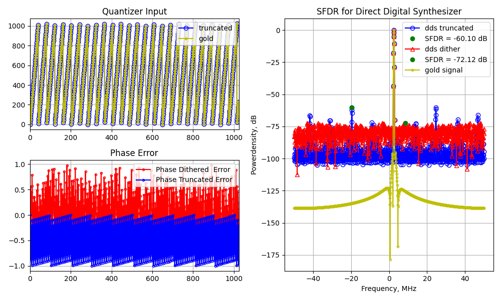
To illustrate phase truncation, let's consider the following example. To generate sinusoid with $f_{out}$ = 2.463 MHz for $f_{clk}$ = 100 MHz and $N$ = 10 the required phase increment is given by:
$$\Delta \Theta=\frac{2.463e6\cdot 2^{10}}{100e6} = 25.22112 $$
Input and ouput of the Quantizer:
Phase truncation involves discarding the fractional part of the calculated phase (using the floor function in mathematics), thereby impacting the dynamic range of the output waveform.
2. Spurious free dynamic range (SFDR)
The Spurious-Free Dynamic Range (SFDR) is the strength ratio of the fundamental signal to the strongest spurious signal in the output. SFDR defines the purity of signals, which is crucial for various applications.
2.1. Truncated phase
When considering phase error due to truncation, a noticeable regularity can be observed, causing significant spurs in the spectrum of the output signal.
In the example above, the largest spur restricts the Spurious-Free Dynamic Range (SFDR) to -60 dB. This corresponds to a dynamic range of 60 dB for a lookup table with a depth of $2^{10}$ (6 dB per bit)
2.2. Phase dithering
Phase dither is a deliberately applied form of noise designed to randomize the quantization error caused by phase truncation.
Randomizing the quantization error allows for an increase in SFDR by 12 dB (-72.12 dB).
2.3. Taylor series correction
The Taylor series correction involves exploiting the linear approximation of DDS output through the use of Taylor series:
$$ f\left ( x \right )=f\left ( a \right )+f{}'\left ( a \right )\left ( x-a \right )$$
Approximating the DDS output using Taylor series allows for an increase in SFDR by 40 dB (-99 dB in the example).
3. DDS Signal Analysis
To assess the quality of synthesized waveforms, a signal with linear frequency modulation (chirp) is considered. The chirp parameters are set as follows: frequency deviation is 10 MHz (ranging from 2.0 to 12.0 MHz), the duration is 5.12 microseconds, and the calculated slope rate is 1,953,125,000,000 Hz/s.
Parameters to be evaluated:
1.Amplitude stability
2.Frequency accurancy and spectrum purity
3.Chirp slope accurancy
4.Chirp phase (instantaneous frequency) linearity
All the parameters to be checked are for synthesized chirp with phase dithering and Taylor series correction, since both approaches allow to reduce spurs in signal's spectrum. The results of the signal analisys are depicted below:
The signal envelope was plotted to estimate amplitude stability. The resulting plot indicates that the signal amplitude at the DDS output, with either phase dithering or Taylor series correction, exhibits monotonic and regular behavior with insignificant deviations. The signal with Taylor series correction shows a slightly wider deviation compared to phase dithering.
Signal power spectrum and instantaneous frequency were used to estimate frequency accuracy and spectral purity. From the plots, it can be observed that signal harmonics are distributed from 2.0 to 12.0 MHz. The phase-dithered signal exhibits slightly worse spectral purity compared to Taylor series correction, as expected since the second approach significantly increases Spurious-Free Dynamic Range (SFDR).
Linear regression was applied to estimate chirp slope accuracy and phase linearity. The estimated chirp slope is 1,960,784,003,708.79 Hz/s for Taylor series correction and 1,960,430,985,807.44 Hz/s for phase dithering, both close to the calculated value. The intercept in linear regression denotes the start frequency for the chirp signal, almost 2.0 MHz for both outputs. A correlation coefficient (R-squared) close to 1 indicates a strong linear relationship despite the standard error (Std Err), which can be reduced by increasing the depth of the LookUp table.
Conclusion: The post elucidated the primary principle of Direct Digital Synthesizer (DDS), delving into two pivotal techniques, namely phase dithering and Taylor series approximation, employed for the elimination of spurs. All equations and algorithms pertaining to the enhancement of Spurious-Free Dynamic Range (SFDR) were substantiated through a mathematical model implemented in Python. The corresponding Python code is provided below for reference. The signal analysis revealed that both phase dithering and Taylor series correction contribute to a stable amplitude, accurate frequency response, and precise chirp characteristics, with each approach presenting distinct trade-offs in terms of spectral purity and computational complexity.


